Cabin Design Project
Livani Balakrishnan
TDJ2DO0-A
RATIONAL
The cabin design project assigned was an enjoyable new concept to experience.
This task involved a step by step procedure that was followed. First, before
beginning ideas and sketches were developed into thumbnail designs. Thus,
allowing a vast variety of concepts to choose from. From these plans, the most
desired thumbnail was chosen to do a rough sketch. Following, there were four
different elevation drawing that were needed to be accomplished. It included an
image of the front, two sides and back views of the structure. Each elevation
drawing was to be finalized with accurate measurements that were scaled and
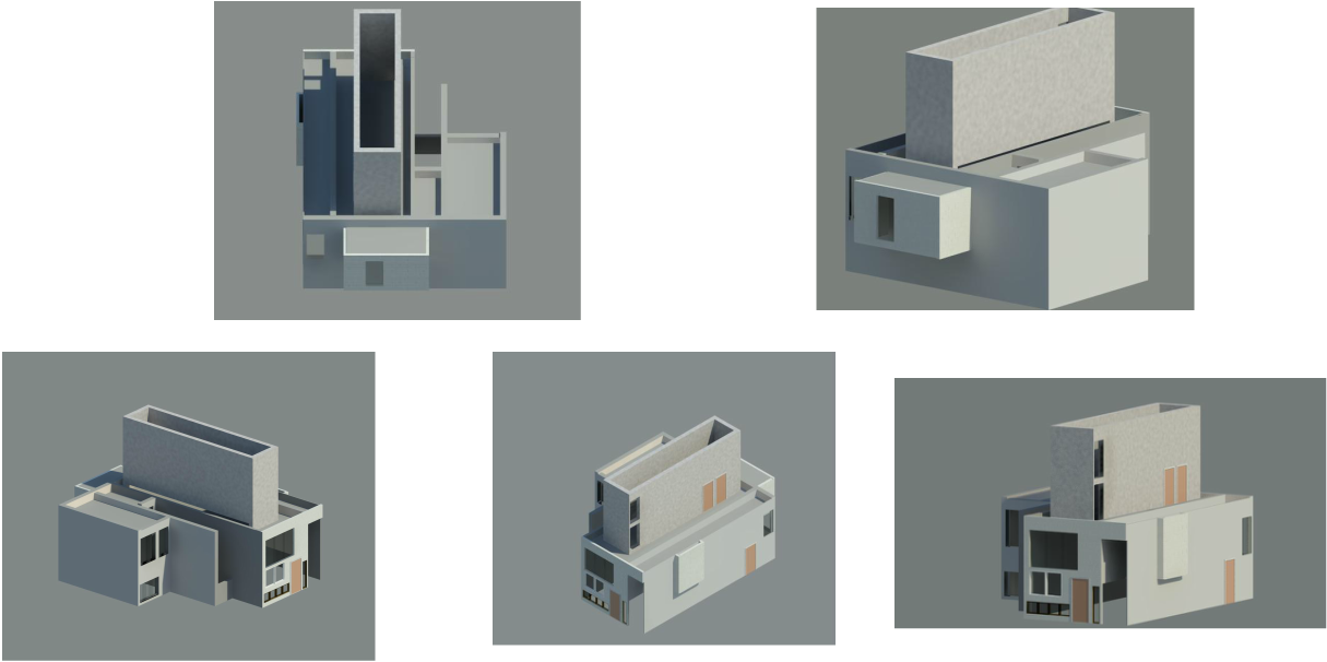
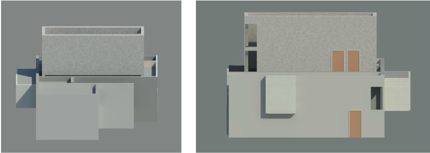
textures of the building. Next, isometric drawings needed to be done. This is a
three dimensional view of the structure. This also needed to include measurement
and texture. In addition, all images were to be neat and centered with the page.
After completing this portion of the task, Revit, a computer program, was used
to actually construct the cabin. This program included different materials to
use to allow for the desired settings. In completion, the cabin was rendered, in
attempts to make it appear actual, opposed to the outlines viewed prior to this
transformation. Although, the process of this assignment was intriguing, it had
brought difficulties to emerge.
During the course of the activity there were many aspects in which there were
challenges. Creating ideas for the thumbnails were not as difficult. However, in
drawing the elevations and isometrics there were obstacles in neatness and
scaling the measurements accurately, according to the page. These situations
were overcome with the aide of time. After practicing with a few rough copy
drawings, more time was taken into creating neater and thinner lines. With some
patience, the effort that was delivered was seen in the result of the design
elevations and isometrics. In drawing these designs, another challenge was to
determine the center of the page, as the cabin required to be fixed upon the
page. Although it could easily be done when sketching the elevation drawings, in
the case of the isometric image, it was much more difficult. Furthermore, since
this would be the first encounter with using Revit, it was confusing to operate
functions of the necessary settings. For instance, it was difficult to do the
exact measurements on Revit that was desired. In addition, it was tough to
generate certain concepts or attachments to the building. Moreover, the
coordinating of the materials, including the walls for example, were not
challenging in the manner of difficulty but took time to figure out what was
appropriate. Conversely, these challenges were crossed and the cabin was
completed.
The cabin designed by myself was a simple concept. There was the main
building connected to a smaller building that allowed passage into another area.
The smaller building ran alongside the main building however the ceiling stops
part way leaving an open area. The building attached to it, it shorter in length
in comparison. The main building has two attachments at back and nearing the
side of the structure. However, these do not reach the ground level, but act as
open area on the interior. On the roof of the main building there is a second
level. In addition, on the roofs of the entire building there are solar panels.
These act as the energy source for the building. They harness the energy from
the sun and transform it into energy to power and operate the functions of the
cabin.
Thumbnail Designs
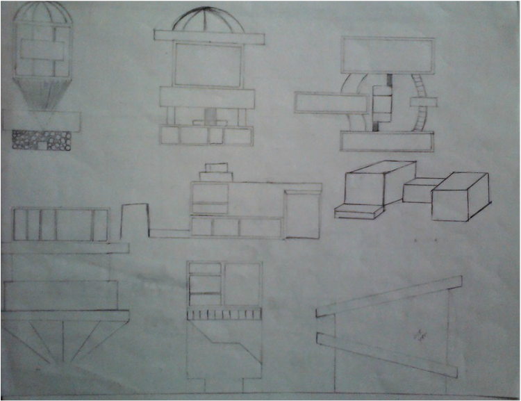
Sketch
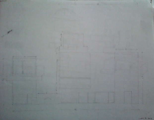
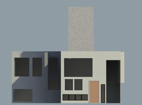
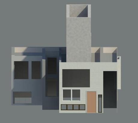
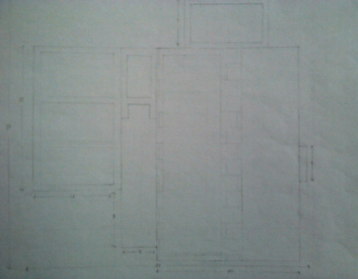
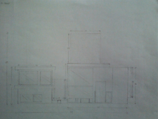
Elevations
Top
Right Side View
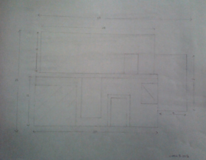
Back
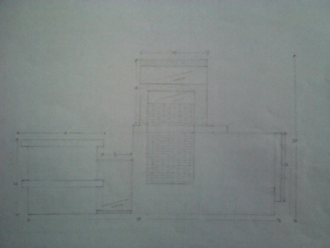
Front
Cabin Design